
DK0A Contest Crew
Email: info (at) dk0a (dot) de
Antenna Switch
The Antenna Switch
After our moderate results in May 2003 (48th place) we changed the location without changing the station or the antennas to see how big the influence of the QTH is and so advanced to the 10th place in the July contest.
To improve our results in September, we tried a new setup: We installed two newly created groups of antennas, each with 4x5el vertically stacked. To learn more about these, please look here. One group was heading north, the other was heading east. Both were connected to a quarter wave match which in turn was connected to the PA.
Normally we sent and received with both antennas. But to focus on one direction, the operator had the choice to use each of the groups separately by pushing a button on a small control unit. So the operator was able to use both antennas, only the "north" one or only the "east" one. This switching was done by the use of seven coaxial relays (see below).
The use of only one group increased the received signal strength of roughly 1 S-meter step. The use of both groups increased the angle of reachability. So we constantly switched around :-)
Secondly another (third) antenna was connected to our second transceiver. This antenna was equipped with a fast rotating motor and while the first operator was doing the QSO, the second operator turned the antenna in target direction. When he thought, that the signal was better than that of the first transceiver, the first op switched his transceiver to the third antenna (and back, if the second Op was wrong :-).
To facilitate the "switching" we build a small box to control the coaxial relays.
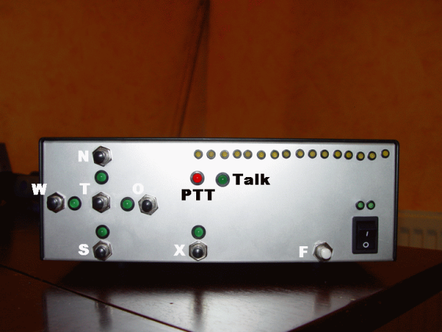
On the front side you can see, that the box is already constructed to use four antennas for four directions. By pressing one of the buttons, the operator switched the transceiver to that antenna. The button in the middle of the four buttons on the left side was used to switch the antennas back to the quarter wave match. To connect the first transceiver to the antenna of the second transceiver the operator used the Button "X". Which antennas were actually used, was displayed by the green LEDs.
To make sure that we don't switch antennas accidently, the box checks the PTT and ignores any actions while the PTT is active. On the other hand, the box inhibits the use of the PTT while the coaxial relays are changing the connections. Both situations are indicated by the red LED.
To carry all this out the control unit implements a sequencer to handle the PTTs of up to four components (e.g. transverter, driver PA, PA). After activating each component, the green LED indicates that the system is now ready to send.
The control unit itself is highly configurable. We use an atmel 90S8535 microcontroller to assure the correct procedure. The microcontroller handles all the inputs (push buttons, PTT input), output (LEDs, PTT outputs, coaxial relays) and security timings (e.g. releasing the PTT block after all coaxial relays are in their end position). Therefore it has 16 MOS-FET port drivers, 7 of them were connected to the seven relays. The status of the port drivers are displayed by the row of yellow LEDs (see above).
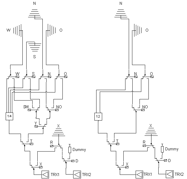
On the right side of the following scheme you can see the setup we used in the September contest (the left side is for future use :-).
The coaxial relays were screwed to a shelf, which you can see on the next picture. The transceivers and antennas were all connected to the relays on that shelf. Well, ok, we will not get a design award for that, but it worked rock solid.
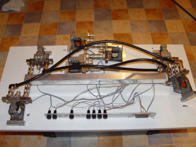
In the middle you can see the quarter wave match we also build on our own and which was directly connected to the coaxial relays.
What comes next? We don't know yet. We learned a lot in the last contest and will build some new black boxes. Perhaps we will use four antenna groups next time - or perhaps something completely new ...