DK0A Contest Crew
Email: info (at) dk0a (dot) de
Antennas September 2003
Antenna installation
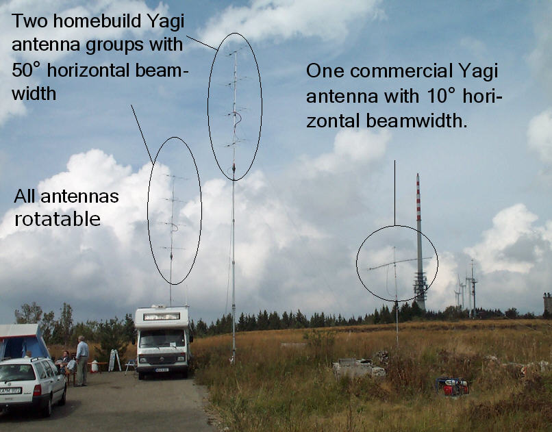
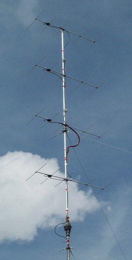
In september 2003, during the IARU-Region-1 VHF contest, we used nine antennas on three portable towers. Two of them carried four DK7ZB 5-element yagis vertically stacked. On the third tower was a single Cushcraft 17-element yagi. The left picture shows all antennas together and the right picture shows one of our yagi group in detail. The vertical distance between two yagis is 1.6 m.
The DK7ZB 5-Element Yagi
| Element... | Reflector | Radiador | Director1 | Director 2 | Director 3 |
|---|---|---|---|---|---|
| ...length | 1022 mm | 960 mm | 910 mm | 915 mm | 882 mm |
| ...diameter | 10 mm | 10 mm | 10 mm | 10 mm | 10 mm |
| ...position | 0 mm | 410 mm | 815 mm | 1475 mm | 1970 mm |
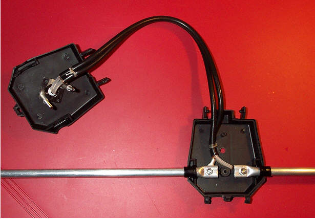
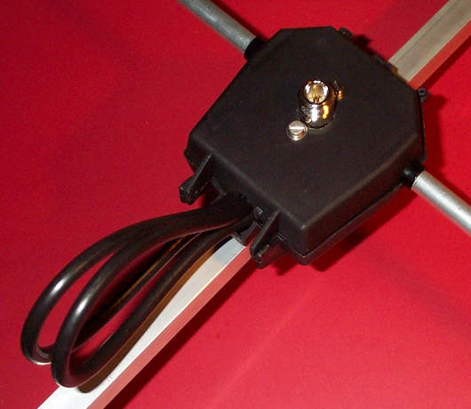
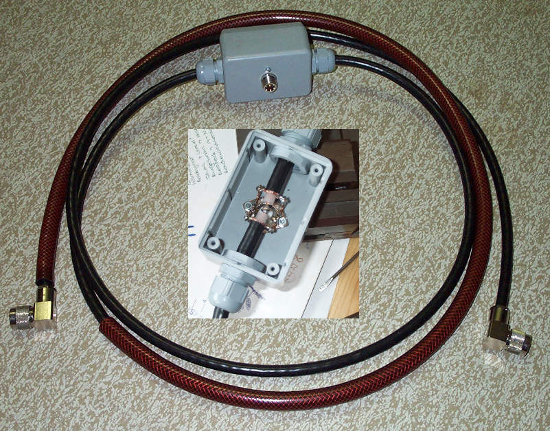
We build this Yagi according to a proposal by DK7ZB. Please look at http://www.qsl.net/dk7zb for the details. The most important features are: 2 m boomlength, 9 dBd gain, front-to-back ratio > 20 dB, 50° horizontal beam width, 60° vertical beam width. The feedpoint impedance of the driven element is 28 Ohms. This impedance is transformed to 50 Ohms by a quater-wavelength matching section build of two 75 Ohm coax lines in parallel. The following pictures shows the connection box (open and closed) of our yagi together with the quater-wavelength matching section.
Our group of four DK7ZB 5-Element Yagis
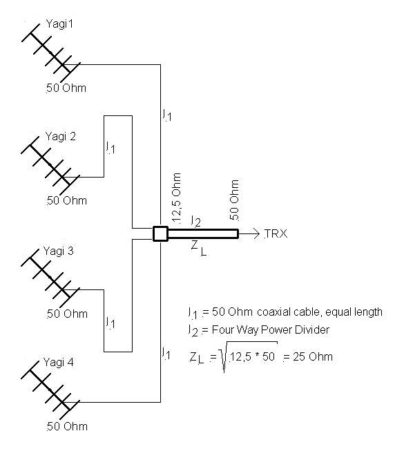
In order to increase the gain over that obtainable from one DK7ZB Yagi we stacked four yagis. The increase in gain is due to the reduction in vertical beamwidth. The gain of the yagi group is about 15 dBd. One method to connect four yagis is using a four way power divider. All lines between the power divider and the yagis must have the same length. This results in an inappropriate layout. That's why we looked for another solution.
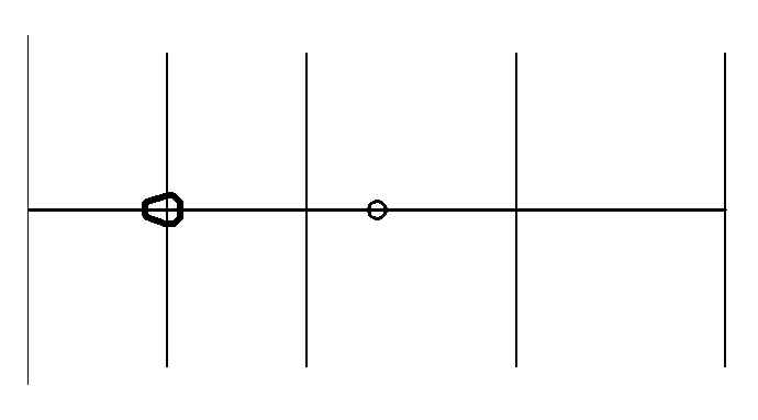
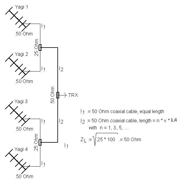
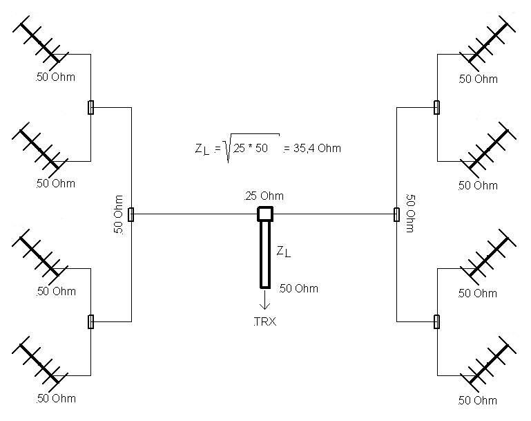
The following figure shows how we solved this problem. The yagis are connected two by two by three 50 Ohm coax lines. The first line connects Yagi 1 and Yagi 2. The second line connects Yagi 3 and Yagi 4. A third line is used to connect both groups. The impedance at the middle of line 1 and 2 is 25 Ohms. This impedance is transformed to (100 Ohms + 100 Ohms)/2 = 50 Ohms by the third line. Line 1 and 2 must have the same length. Line 3 is a quater-wavelength matching section.
Such a matching line is easy to build. We used a piece of 50 Ohm coaxial line with N-plugs at both ends and a N-socket in the middle of the line. The connection to the N-socket is protected by a small plastic box.
Connection of two Yagi groups
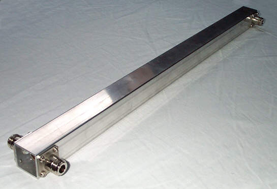
I order to run both Yagi groups together at one Transceiver we build a two way power divider.
The power divider's inner and outer diameter was calculated by means of the RF design software "AppCad". This software is available free of charge by Agilent Technologies at http://www.hp.woodshot.com.
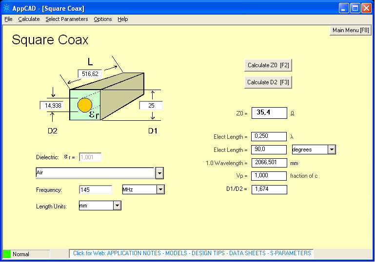
This is a picture of our homemade two way power divider.